Coordinate Systems

Believe it or not, all of the Math we’ve been discussing up until now has been leading us to this point. Now we have enough knowledge to introduce the Coordinate_space. In the Dubious Engine, a Coordinate_space represents an object’s position and rotation. Given what we’ve learned about Vectors, Points, and Quaternions, I hope it’s not surprising to see the data in the class:

class Coordinate_space {
    Point               m_position;
    Unit_quaternion     m_rotation;
};

That’s all we need to describe where an object is, and which way it’s facing. Before we take a look at how all the pieces come together to move one of these things around, let’s discuss “handedness.”

Right Handed Coordinate Space

I’ve been purposefully glossing over this subject up until now because I thought it was too much detail. But now that we’re finalizing our Math section, it’s time to discuss the ambiguity in our Z axis. From your earliest Math classes dealing with X and Y axis you’ve probably been told that the X axis goes from left to right, by which I mean +100 is further to the right then -100. Likewise you probably see the Y axis as going up (ie +100 is higher up then -100). But what about the Z axis? Does it point out of your computer screen towards you, or from you into the screen? Well it turns out that both systems are equally valid, and different Math packages use one way or the other. It’s not a big deal to convert between them, but it’s definitely a lot simpler to pick one and stick with it. OpenGL and Bullet Physics both use a system where the positive Z axis points from your screen out to you (ie your nose is +100 and the area behind your screen is -100). I decided I wanted my coordinate space to match OpenGL so it would be easy to draw what I was building in my Physics Engine.

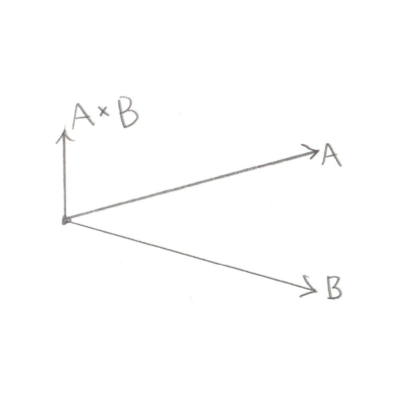
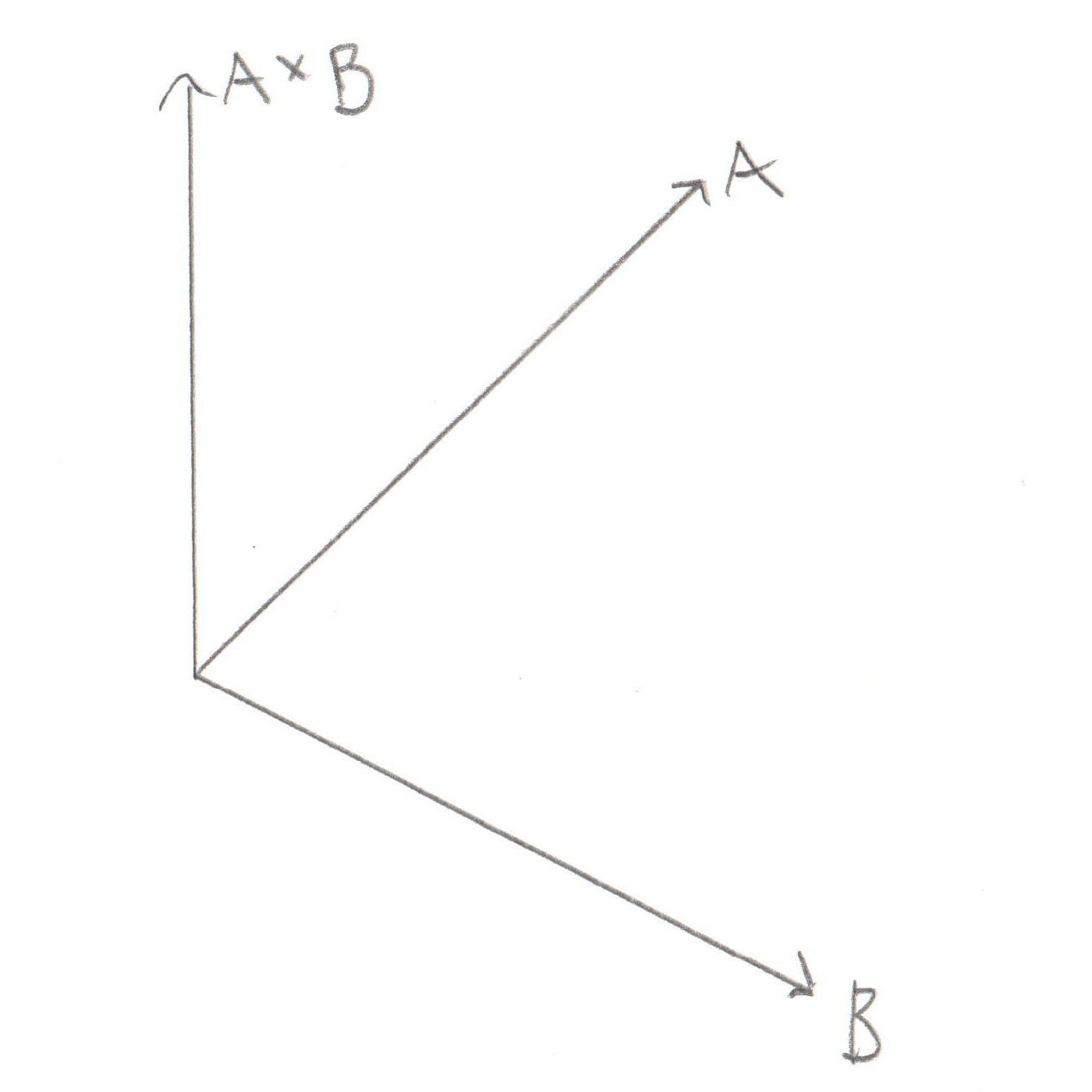
What’s this have to do with hands? Well to help us give a name to the two different ways of orienting your Z axis, someone came up with a way to illustrate the X, Y, and Z using  your fingers. If you hold up your right hand and point your thumb along the +X Axis, and your index finger along the +Y Axis, you can then point your middle finger at your nose and call that the +Z Axis. This is a Right Handed Coordinate System. If you try to do the same thing with your left hand you’ll see that your middle finger points away from your nose, a Left Handed Coordinate System.

There’s one more hand trick that might even be more important when representing rotations using Axis and Angle. You may have noticed that up until now I’ve said that the Axis is the Vector you rotate around, and the Angle is the amount you rotate, but I never specified which direction to rotate. By using our hands we can finally answer that question. If you represent your Axis Vector as running along your thumb (the thumb nail is +100, palm is -100) then a positive rotation is the direction in which the rest of your fingers curl when you make a fist.

Let’s put all those bits together with an example. Let’s demonstrate a positive rotation around the +Z Axis using the Right Handed Coordinate System. Start by holding your right hand in front of your face with all of your fingers open and with your thumb pointing at your nose. Your thumb now represents the positive Z Axis. Curl your fingers into a fist, that is positive rotation. You should see your fingers curling counter clockwise. When you see information about a Right Hand Coordinate System online you’ll often see that positive rotation is counter clockwise.

If you’re trying that out and it’s not working as expected, re-read this and try again. It’s worth getting right because bugs in the direction of rotation are really hard to figure out. The more you understand it now, the easier your life will be.

Actions on a Coordinate_space

Turning our attention back to the Coordinate_space, let’s look at the functions it supports. At the core, it has some transform functions that serve to convert global Points and Vectors to local Points and Vectors, and vice versa. The usage of types makes these very transparent:

Vector        transform( const Local_vector& v ) const;
Local_vector  transform( const Vector&       v ) const;
Point         transform( const Local_point&  p ) const;
Local_point   transform( const Point&        p ) const;

The code that drives these is based on Quaternion magic, so I can’t pretend to understand everything about why it works, but I am comfortable that it does.

As you can see, there’s no need to specify in the function name what you’re transforming from and to, we just use the type system to do the right thing. This is another good argument for why a Vector and a Point should be different. Since Vectors have no position, the transform function simply rotates them. And since Points do have a position, the transform function rotates them and moves them. For example, if we have a Coordinate_space that is moved to (1,0,0) and rotated 90 degrees around (0,1,0), and we have a global point at (2,0,0), by now you should be able to reason that if we converted that Point into the Coordinate_space it would be at (0,0,1). Try out a bit of invisible knitting yourself, to see if you get the same result.

Aside from these helper type functions, a Coordinate_space has the usual translate and rotate things  you’d expect. I won’t dwell on those, they do what you’d expect, they move and rotate the Coordinate_space. Their implementation is straight forward with the help of the transform functions.

The last function is one that I find myself using a lot, it’s this:

std::tuple<Unit_vector,Unit_vector,Unit_vector> get_axes() const;

This one returns the global X, Y, and Z axis for the Coordinate_space. How is that useful? Let’s say you’re flying in your space ship and you want to fire a laser. What direction is the laser going to go? Clearly it is going to fly straight out from the front of your ship. And what direction is straight out? Well that would be along the +Z Axis. So with this simple function it’s easy to grab the direction in which the laser should fly. In normal usage you would create a new Laser object, drop it into your game, and set it’s velocity to be a Vector of some magnitude (the longer the faster) directly along the +Z Axis that this function returns.

So there you have it, our long journey through the Math of the Dubious Engine is now complete. We have created simple ways to deal with Points, Vectors, Rotations, and Coordinate_spaces. Now we have enough tools at our disposal to go ahead and start talking about the point of this whole thing: Physics.

 << Using Types Contents  Linear Motion >>

Rotations

Now that we’re starting to get somewhere with Vectors and moving around in 3D, let’s turn our attention to the next topic, rotations. (Get it? “Turn our attention.”) Rotations in 3D are pretty awesome, it’s surprising to me how many clever ways there are to represent them. Unfortunately they all pretty much suck for writing a Physics Engine, but let’s take a look at them and discuss the pros and cons. If you want to jump to the answer, it’s Quaternions, but let’s see why.

Caveat Emptor: I am not a Math major, I am self taught on this stuff. As I’ve learned new things, I’ve often found that my previous understandings were incorrect. The web is awash in articles about 3D rotation that are simply wrong, this may be just another example.

Euler Angles

Apparently this is pronounced “Oiler,” who knew? These are appealing because they’re the simplest to understand. If you’ve played any flight simulators or spaceship fighting games then you already understand them, they’re pitch, yaw, and roll. If you haven’t played those kinds of games then I feel sorry for you. Here’s a refresher, imagine you’re flying an airplane, these angles are:

  • Pitch – is the nose pointing up or down
  • Yaw – this isn’t used much in airplanes, but it’s turning left and right while keeping the wings level. It’s how a car turns
  • Roll – when planes turn one wing goes up and the other goes down, this is roll. Hopefully it’s never used in a car.

This is probably a good a time as any to try to start thinking in terms of X, Y, and Z axis. For our discussions the X axis moves left to right. The Y axis moves up and down. The Z axis moves forward to back. Pretty simple stuff, right? For Euler Angles to make sense we also have to think about the planes that the axes define. In this case I mean plane like a flat surface like a table top or a wall, not the kind you fly in. Take a moment to convince yourself that any 2 axes define a plane. The X and Z axes together define planes like the floor or table top. The XY plane would be a TV you’re watching. The YZ plane defines the walls to your right or left side.

So anyway, if you say your pitch is 45 degrees up from the XZ plane (a table top), 45 degrees to the right of the YZ plane (a wall to your left or right) and then 180 degrees of roll, that would mean you’re facing up and right, and you’re flipped upside down. That’s Euler Angles. Like I said, it’s not very hard to understand. However it suffers from some pretty serious limitations. The first of which is that the order of application is important. If you do the roll first or last you will end up in a completely different place. In our previous example if you started by rolling 180 degrees then you’d be upside down and your concept of “up” would be different. So from there if you went “up” and “right” you’d end up in a different place then if you did the roll last. So if you’re tempted to write a rotation function like

void rotate( float pitch, float yaw, float roll )

Just stop! Nothing about that interface says in which order the operations will be defined, so you’re almost guaranteed to forget and change your assumption and end up with a horrible bug.

The second major problem with Euler Angles is “Gimbal Lock.” Go to Wikipedia for more information on this one, it’s fascinating but a bit beyond the scope of this. The short version is that while Euler Angles can define every possible rotation, they can’t always be combined. So while you’re perfectly safe representing your current rotation with Euler Angles, if you then want to turn the ship a bit, and maybe spin when a missile hits and you try to combine all of these rotations it might work… or you might end up in a state where the next rotation will be jarring and random.

The third major problem with Euler Angles is Interpolation. This means if you have two different rotations and you want to move some percentage of the way between them, it’s difficult to figure out where that should be. How could this be useful? Well if you know you’re rotating 50 degrees per second and a half a second has passed, how far should you rotate? 25 degrees sounds like an obvious answer. But trying doing this when you’re rotating around all 3 axes at the same time? That’s Interpolation and it’s very hard to do with Euler Angles.

Axis and Angle

This one here is my own personal favorite because it’s just so darned handy. It takes a little bit longer to get used to, but it’s worth the study time. For this system you start with a Vector, and then you rotate around it by the Angle specified. Makes sense, right? Think about a door. They rotate around the axis defined by the hinges, a Vector that points straight up and down. How far they rotate is specified by the Angle. What about if you’re standing straight up and you want to bow? The Axis would be a straight line from your left to right, forming a hinge through your hips. How far you bow around that Axis is the Angle. These start to get a little confusing when you want to rotate around an Axis that isn’t so easy to picture. Like what if the Axis is (1,1,1) that’s sort of a diagonal axis that’s up, right, and back so rotating around that is a little harder to imagine. I often end up holding my hands in front of my face with my fingers pointing in different directions and trying to rotate my arms around them. My wife calls this “Invisible Knitting.”

Another great advantage of Axis and Angle is that it works really well with Cross Products. Imagine you’re pointing directly forward and you want to turn to your right. If you take your starting Vector (forward) and get the Cross Product with your destination Vector (right) you will end up with a new Vector that points straight up. It turns out that this new Vector is exactly the Axis you need to rotate around. And it’s length is proportional to how far you have to rotate, ie the Angle. So yeah, Cross Product and Axis and Angle are made for each other.

So to compare Axis and Angle with Euler Angles I would say that Euler Angles are a little simpler to understand. But that’s about their only win. Axis and Angle may be a bit harder to grasp, but once you become comfortable with them they’re easy. Furthermore they don’t suffer from bugs due to order of execution, and they work really well with Cross Products. Big wins. As far as gimbal lock goes, I think they don’t have this problem. I have to confess I don’t understand all the math on this one, so we’ll chalk that one up as a half point in their favor. Alas Interpolation is still very difficult with Axis and Angle.

Rotation Matrices

I’m afraid if you’ve come here hoping for a deeper understanding of Rotation Matrices then you’ve come to the wrong place. In all my Physics Engines over all my years I have made it a point to never use these. A 3×3 rotation matrix simply has too many numbers in it to make any sense to me. I have no intuitive feel for how Matrices work, so debugging them is basically impossible. The Dubious Engine uses exactly one matrix, and it’s required to pass rotations to OpenGL. I don’t understand it, I just know how to dump my rotation into it.

Here’s the important thing I do know about Rotation Matrices, they also suffer from Gimbal Lock and are hard to Interpolate. So as far as comparisons go, they’re impossible to understand, and suffer from the same exact failures as Euler Angles and Axis and Angles. So why bother learning them?

Quaternions

Enter the Quaternion. For most of my Game Engine life I considered Quaternions to be unknowable. I couldn’t figure out how they worked or how to imagine them, so I just copied some equations I learned online, tested them enough to convince myself they worked, and moved on. However I am pleased to report that after some more study they’ve started to make some sense to me. I’ve recently gone back through my engine and smoothed out some misunderstandings with Quaternions. None of the math changed, so I don’t think I fixed any bugs, but it does make a bit more sense now, which is worthwhile. It’s also a little slower, which is a shame, but worth it for the clarity.

I’m not going to try to write another article explaining Quaternions. I’ve found two that did the trick for me, so I’m just going to send you there and let you learn the same way I did. However I will fill in the starting point that I was missing. I was familiar with “Imaginary Numbers,” which I hope you are too. If not, they’re usually represented as i and are defined as:

i = sqrt(-1)
or
i * i = -1

What I did not know was that there is another kind of number called “Complex Numbers” that are defined as a real number plus an imaginary:

a + bi

I had no idea these existed, and most Quaternion articles start assuming you know them. Luckily not the ones I recently found.

So, at this point, push the pause button on this article, and spend some time learning from these two sources. I am humbled by how well they explain the subject, they do it better then I ever will. When you’re done, feel free to return and we can look at how we can use Quaternions in a game engine:

  • https://www.youtube.com/watch?v=mHVwd8gYLnI – as taught by an actual University Professor. Unfortunately while attempting to speak and write on the blackboard he occasionally messes up an equation, so don’t copy the Math verbatim. Still an Amazing lecture that will get you up to speed very quickly.
  • https://www.3dgep.com/understanding-quaternions/ – the big one. Nothing about it is easy, you will have to re-read it a bunch of times, but it is complete and awesome. In fact, his whole site is awesome, I will be aspiring to be half as good.

Okay, you know know what I do about Quaternions. Here’s how you can represent one in C++

struct Quaternion {
    float w;
    Vector v;
};

From the 3D Game Engine Programming article, we know that in a lot of Quaternion Math, the imaginary component acts as a Vector (with dot products, cross products, scalar multiplication, etc). Luckily we already have a Vector class defined that does these things, so it’s easy to reuse. In fact, all of the math for a standard Quaternion is pretty straight forward, so my Quaternion class is relatively simple, here’s a link, there shouldn’t be any surprises.

How do we use them? Well really for 3D rotations it’s a Unit Quaternion we want to use. These are the kind that represent rotations. They can easily be created from an Axis and Angle like this:

Unit_quaternion::Unit_quaternion( const Unit_vector& axis, float angle )
{
    w = cosf( angle / 2.0f );
    v = Vector(axis) * sinf( angle / 2.0f );
}

So now we can convert from something we’re comfortable with, Axis and Angle, into a Unit Quaternion. From there the math for combining multiple Quaternions to produce an output Unit Quaternion is fairly easy to code up. Lastly any Unit Quaternion can be pretty easily converted back to three axis: X, Y, and Z.

I’ll tell you one major drawback of working with these things though. There is just no way to get an intuitive sense of them. Here’s a pop quiz for you to see how your 3D intuition is developing. Point (with your finger) to Vector (1, 1, 0) and rotate 45 degrees forward around it. If you pointed diagonally up and right and then kind of rolled forward and left a bit, congrats! It might not be perfect, but at least you have a sense of it. Okay, now imagine Quaternion (1, (1, 1, 0)) and rotate around that. That real bit has something to do with half the cosine of the angle, and the imaginary bit is related to half the sine… I have absolutely no idea where to go. So imagine trying to debug this code. Like you notice in your simulation that some cubes are rotating “oddly.” So you set your breakpoint, look at your rotation and see it’s (0.43255, (0.97666432, 0.43234, 0.124535)). What do you do with that?

So in summary, let’s compare Quaternions to the other Rotation representations we’ve discussed. On the plus side, they do not suffer from Gimbal Lock, or bugs due to order of execution. We didn’t specifically discuss Interpolation, but they do it very well, it’s called “Spherical Linear Interpolation” or SLERP and it’s easy to code up. On the negative side they’re very difficult to understand and debug. However this is somewhat smoothed over by the simplicity in converting between Unit Quaternions and Axis and Angle. All in all, they’re a big win, which is probably why most Physics Engines use them.

Here’s the links:

 << Vector Math Contents  Using Types >>

Vector Math

Okay, for this post let’s finally stop talking about the Philosophy behind the class design, and instead look at some math. We’re going to start with the basics of Vector Math and build up a working vocabulary of what we can do with it.

A Vector is a direction and a magnitude, represented by 3 floating points. This could mean something as simple as:

struct Vector {
    Vector( float x_coord, float y_coord, float z_coord )
        : x( x_coord )
        , y( y_coord )
        , z( z_coord )
    {}
    float x;
    float y;
    float z;
};

I’m going to assume that you’re comfortable with the idea of 3D and x, y, and z axis. What do I mean when I say a Vector is a direction AND a magnitude? Well consider these 3 Vectors

    Vector v1( 1, 0, 0 );
    Vector v2( 2, 0, 0 );
    Vector v3( 0, 1, 0 );

v1 and v2 have the same direction, which is directly along the x axis. However v1 is 1 unit long, while v2 is 2 units long. v3 has the same length as v1 (1 unit) but its direction is different, it’s along the y axis.

You’ll remember from my post about Points and Vectors that while Points also have 3 floats, their meaning is different. A Point does not represent a direction and magnitude, it represents a position in space.

Now then, the simplest set of operations on Vectors are addition and subtraction

Vector operator+(const Vector & a, const Vector & b)
{
    return Vector(a.x + b.x, a.y + b.y, a.z + b.z);
}

Vector operator-(const Vector & a, const Vector & b)
{
    return Vector(a.x - b.x, a.y - b.y, a.z - b.z);
}

Vectors can also be multiplied and divided by a scalar (a single float)

Vector operator*( const Vector& a, float b )
{
    return Vector( a.x*b, a.y*b, a.z*b );
}

Vector operator/( const Vector& a, float b )
{
    return Vector( a.x/b, a.y/b, a.z/b );
}

Not much magic here, this shouldn’t be very surprising.

The next bit to consider is a Vector’s length. This can be found using this pair of functions

float Vector::length_squared() const
{
    return x*x + y*y + z*z;
}

float Vector::length() const
{
    return sqrt(length_squared());
}

If you’re unfamiliar with this code you may be wondering why there’s a float length_squared() function. The reason is an optimization. Now I’m definitely not one to optimize prematurely, and I have never actually profiled how much more time it takes to perform the extra square root functions, however there are times when you really don’t care how long the actual length is, you just need to compare it to another Vector’s length. For example, given three Vectors A, B, and C is the length from A to B longer then the length from A to C? We don’t care what the length is, we just need to know which is longer. Comparing the length_squared will get us the same result.

Okay, now let’s move on to something that you might not remember so well from High School Math, the dot product and cross product.

float dot_product( const Vector& a, const Vector& b )
{
    return a.x*b.x + a.y*b.y + a.z*b.z;
}

Vector cross_product( const Vector& a, const Vector& b )
{
    return Vector( (a.y*b.z) - (a.z*b.y), 
                   (a.z*b.x) - (a.x*b.z), 
                   (a.x*b.y) - (a.y*b.x));
}

So the math isn’t so daunting, but what do these things mean? Well that starts to get interesting.

Dot Product

The dot product of 2 Vectors is (sorta) the length of the projection of the first vector on the second one. For now let’s not dwell on the actual value of the length, but let’s get an intuitive feel by looking at two examples:

Large Dot ProductSmall Dot Product

In the first image you can see that the two Vectors mostly overlap each other, so the dot product is “big” (again, not worrying about the actual numerical value). In the second image, the two Vectors don’t overlap much, so the dot product is “little.” By checking to see if the dot product is “big” or “little” you can start to get an intuition of how much the Vectors overlap.

What if the Vectors don’t overlap?

In this case the dot product will be negative. How is this useful? Turns out it’s really useful. Let’s say you’re writing a space ship video game (I love space ship video games) and you have one Vector pointing directly forward from your ship. Then you have another Vector pointing towards an attacker. Is the attacker in front of you or behind you? Seems like a pretty important thing to know. Well if the dot product of the two Vectors is positive then the attacker is in front of you. If it’s negative then the attacker is behind.

That’s not a bad start, but what about the actual length itself? I’ve been saying the dot product is “sorta” the length, well what’s the actual length? It turns out to be related to the cosine of the angle between the two Vectors

// not actually valid C++
cos(angle) = dot_product(a,b) / (a.length() * b.length())

Okay, let’s try to give you a gut feel for how this makes sense. Do you remember your cosine curve from trigonometry class? If not let me highlight the important bits:

Cosine Curve

angle (degrees) cosine
0 1
90 (radians: pi/2) 0
180 (radians: pi) -1
270 (radians: 3pi/2) 0

Now think about our two Vectors. If the angle between them is 0 then they completely overlap, so the projection of one Vector on the other is exactly the length of the Vector itself (so when you divide it by the Vector length you get 1, which corresponds to our cosine table). Now how about if we look at the dot product of two Vectors at 90 degrees to one another. There is no overlap at all, the length of the projection is 0, which is exactly the value of the cosine of 90 degrees from our table. If the two Vectors point in exactly the opposite way from one another, then the overlap is negative 1, etc etc. I don’t want to kick this dead horse, but getting an intuitive feel for this will be very helpful. If you feel like your head is spinning a bit, get yourself a pencil and paper and re-read this section while drawing out your own examples. Trust me, it’s worth the time to have a feel for this.

Cross Product

So with the dot product put to rest it’s time to tackle the big one, the cross product. Unfortunately this one is a bit harder to picture because the cross product of two Vectors is yet another Vector. To start to visualize this, first get comfortable with the fact that any two Vectors describe a plane. It doesn’t matter how you draw them, two Vectors with the same origin will always be in the same plane. The cross product of any two Vectors is a third Vector that is perpendicular to that plane. Again, let’s not worry about how long that Vector is, it’s important to know that it’s perpendicular to the other two. The length itself is proportional to the angle between those two Vectors:

Small Cross ProductLarge Cross Product

Notice that in the first drawing the two Vectors overlap a lot (ie their dot product is “big”) and the third Vector, the cross product, is not very long, it’s “little.” Conversely in the second drawing the two Vectors don’t overlap much at all (dot product is “little”) and the third vector is long, or “big.”

So how is this useful? Well to understand that we need to understand Rotation Vectors, which I will be covering in a later section. I don’t want to confuse this section too much, so for now just trust me that the cross product is helpful. After you’ve read about Rotation Vectors, come back here and see if you can figure it out.

How about we try to put a concrete number on how “big” or “little” our cross products are? Well in this case the math is:

// not actually valid C++
sin(angle) = cross_product( a, b ).length() / (a.length() * b.length())

Okay, so in this case the length of the Vector created by the cross product is related to the sine of the angle between the Vectors. How much do you remember your sine curve? Here’s the important bits:

Sine Curve

angle (degrees) sine
0 0
90 (radians: pi/2) 1
180 (radians: pi) 0
270 (radians: 3pi/2) -1

In this case when the two Vectors completely overlap, the length of the third Vector (the cross product) is 0. As the angle between them grows to 90 degrees, the length of the third Vector grows to the maximum. As the angle goes past 90 degrees, the length of the third Vector (the cross product) goes back to 0. Again, if you have trouble imagining this in your head, get a pencil and paper and try drawing out a few examples. As with the dot product, it’s important to have a good gut feeling for this

Okay, that was a lot of math, but hopefully worth it. Once it starts to make sense, have a look at my code to see how it can be written. Again, for now ignore that my Vectors and Unit_vectors are templates, we’ll discuss why that is in a later post:

  • Triple – the basics, addition and subtraction
  • Vector – multiplication with scalars and lengths
  • Unit_vector – most operations result in non-unit Vectors
  • Vector_math – dot product and cross product
 << Vector Types Contents Rotations >>

Vector Types

My previous post was short on Math and code, and long on Philosophy. Just what is a Point and a Vector? How do they differ? How are they the same? Well I’m afraid we’re gonna start this one off in a similar manner. However this time the topic is Vectors and Unit Vectors. For those that are newer to this topic, a Unit Vector is simply a Vector with a length of 1. So with an explanation that simple, it should be pretty straightforward to write the code right? Well… no. Just as a Point could be written as a Vector, a Unit Vector could be written as a Vector, but doing it that way doesn’t always fit. I have tried a number of different techniques to represent these things, I’ve made them exactly the same class, I’ve used typedefs, I’ve used inheritance (even private inheritance). In my current Physics Engine, they’re completely different classes. Let’s take a look at why.

The first reason is one of class design. A pretty standard function of a Vector is float length(). This is useful for a Vector, but completely meaningless for a Unit Vector. The very definition of a Unit Vector is that its length is 1, so why have a function? Still while that’s a silly function to have, it wouldn’t break anything. But how about void set_length( float new_length )? This could be useful in a Vector, but it’s forbidden in a Unit Vector. Similarly any of the +=, -=, *=, /= operators don’t make any sense for a Unit Vector. Addition would take a Unit Vector and add another Unit Vector to it, creating a Unit Vector that has a length of 2. And since the definition of a Unit Vector is that its length is 1, this is clearly broken.

How about converting between the types? Taking a Vector and setting the length to 1 (ie making it a Unit Vector) is called “normalizing.” If you only have one general Vector class, how would you write a normalize function? You could have it so that the function acted on the Vector itself (and thus subtly changed it to a Unit Vector) or you could have one return a new Vector that is actually a Unit Vector. Neither of these are very satisfying solutions because both of them result in a promise that the compiler can not check. But with an actual Unit_vector type you can make a constructor like this:

Unit_vector( const Vector& copy );

In that case it’s very obvious that you’re creating a normalized version of the passed in Vector. And what’s better is that the compiler can enforce that you have an actual Unit Vector and not just something that a comment says is a Unit Vector. Never trust the comments.

The third reason for making them different is an optimization. There are a lot of functions that are quite complex when dealing with Vectors, but actually very simple when dealing with Unit Vectors. If your two types are not actually different types then you’re forced to always write the complex version, even when you know that your inputs will always be Vectors of length 1. Or what’s worse, you could write functions that assume the inputs will always be Vectors of length 1, and put a big comment on them that says “Only call this with vectors of length 1” and then a few weeks later you’ll call it with a Vector of some other length and spend days trying to figure out why it doesn’t work.

For a simple example of this, consider the case of trying to find the angle between 2 vectors. If you use dot products then the equation looks like this (don’t worry if you don’t know what a dot product is yet, we’ll cover that soon enough):

cos(angle) = dot_product( u, v ) / (u.length() * v.length())

Finding the length of a Vector is sort of expensive, it involves a square root. With a Unit Vector you already know what the length is, it’s 1. So this becomes the much simpler:

cos(angle) = dot_product( u, v )

As you can see, you’ve removed two calls to Vector::length(), a multiplication, and a division. More subtly, you’ve also removed the need to check for zero length Vectors and the possible division by zero.

So there’s the end of the Philosophy for today. Much as a Point and a Vector are best represented by entirely separate things, so too are a Vector and a Unit Vector. You can see this in my code. Notice how in the Unit_vector class, operations that will change the length return Vectors. This tells the compiler that the type is changing, so you can enforce the run time length at compile time. This will help keep out the bugs and confusion.

 << Points and Vectors Contents  Vector Math >>

Points and Vectors

I’m gonna start off our discussion of Physics Engines with some posts about the Math that makes them tick. Don’t worry, I don’t have a degree in Math, so these posts will be long on rambling sentences, and short on Greek symbols. For this one I’m gonna skip the equations all together and just try to talk about the meaning of the most basic types in a Physics Engine: Points and Vectors.

There isn’t much that’s more fundamental to a Physics Engine then Points and Vectors. And for this reason, it’s important to spend some time getting them right. In my path to the Dubious Engine I have actually written a basic Vector library a handful of times. I even wrote one in Haskell to see if it did a better job of handling some of the awkward language edge cases that kept creeping up with C++. What is it about Points and Vectors that are so hard to get right? Well looked at from one angle, they’re pretty much exactly the same thing, 3 floats representing X, Y, and Z coordinates. But looked at from another angle, they have absolutely nothing in common. A Point represents a position in space, or where an object is. A Vector represents a direction and a magnitude, which isn’t really easy to summarize. Can you represent a Point with a Vector? Sure you can, like I said, they’re both 3 floats. But should you use the same class for both? I’d argue that you should not. Let’s discuss why.

Take a moment to consider addition. Does it make sense to add two Vectors together? Yes, absolutely, it’s entirely natural. If you had high school Physics I imagine you spent a lot of time adding Vectors. The mechanics are simple, you just add each of the three coordinates to each other. But what about Points? Does it make sense to add two Points? Surprisingly, no. Sure the math behind it is trivial, it’s the same as with a Vector. But does that have meaning? Let’s say you live in Philadelphia and I live in New York? Both of our positions in space can be represented as Points. But what does it mean to add Philadelphia to New York? It doesn’t mean anything. What would the locations of Philadelphia plus New York represent? I couldn’t even guess. So if addition of Points is meaningless, surely subtraction is too? Oddly enough, subtraction does have meaning. If you take Philly and subtract New York you are left with a Vector that defines the direction and distance from New York to Philadelphia. Remember that a Vector is a direction and magnitude. So this Vector’s direction would be South West, and the magnitude would be about 100 miles. Now if you start with the New York Point and you add this Vector, the result is the Philadelphia Point. Let’s summarize this:

  • Addition and subtraction of Vectors is correct
  • Addition of Points is meaningless
  • Subtraction of Points results in a Vector
  • Addition of a Point and a Vector results in a Point

This probably isn’t the result you were expecting when you first started thinking of Points and Vectors. I can tell you from experience that it took me many years to start thinking along these lines. Can you write a Physics Engine that ignores all of this and just uses a Vector for everything? Of course you can, my first few attempts did exactly this. However I found I was always creating bugs where I’d write an interface that expected a position, but I would eventually send it a Vector, and the whole thing would fail and I’d spend a lot of time trying to re-learn the algorithm to understand why. With this new representation I’m much clearer on the roles of Points and Vectors and it helps me keep things straight.

The Code

So with that in mind, how do we write the code? You could be tempted to just make them exactly the same thing, and just use a typdef to give them different names. After all, the actual mechanics of addition, subtraction, and equality are the same. But functions like get_length() make no sense with a Point, but are fundamental to a Vector, so it’s best to avoid this approach. You could be tempted to use inheritance, and move the common functionality to the base class Point and put the Vector specific functionality in the Vector. This is a little cleaner in that you can reuse common code, but the polymorphism is awkward because inheritance represents an “is-a” relationship, and as discussed above, a Vector is not a Point. Another trick you could try is composition, where a Vector just contains a Point, but this leads to circular dependencies in your code. In order to implement Point subtraction a Point must depend on a Vector, but in order to implement a Vector it must depend on a Point. This will really piss off your compiler, which is generally not a good thing to do.

So this leads us to the solution I ended up with, a third class called a Triple, which is nothing more then an abstract thing that contains 3 floats. This Triple isn’t even a class, it’s just a lowly struct, and it implements the absolute basics, addition, subtraction, and equality. Both a Point and a Vector contain a Triple, and a lot of their basic functions are implemented as a simple pass through. They both build on the Triple to implement their type specific functionality.

Now that you understand my reasoning behind Points and Vectors, it should be pretty easy to understand the code. Here are links to my Triple, Point, and Vector implementations. For now, ignore the templates, we will discuss their usage later.

  • Triple – Simple struct of 3 floats. Handles basic math and equality
  • Point – Represents a 3D point in space.
  • Vector – Represents a direction and magnitude.
 << See Also Contents  Vector Types >>